Specialty crops such as fruits, nuts, and vegetables require irrigation to produce high quality crops. However, irrigation systems are rarely run continuously, and systems idle between crop rotations, seasons, and/or during maintenance. Any time equipment remains idle and exposed to elements like weather extremes, critters, and other unforeseen maladies, there is significant potential for damage to the system. Performing a thorough preventative maintenance check before starting the irrigation system will identify whether the system has been compromised and provide an opportunity to correct problems before the system is in demand.
Drip irrigation systems are a popular way to supply plants with water and are usually used to add fertilizers, pesticides, and, in the case of acidic-soil-loving plants like blueberries, acid. Delivering both water and chemicals through a single system is called "chemigation."
A drip irrigation system includes a water source (surface or well), power unit, pump, back-flow regulator (preventer), filter, pressure gauges, pressure regulators, flow meter, valves, connectors, pipe, tanks, injectors, and drip tube (Figure 1). Before starting the system, perform checks and repairs to ensure that the delivery system is in optimal condition. The following are suggestions that will guide you through a startup maintenance program for your drip irrigation system.
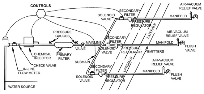
Figure 1. Typical components of a drip irrigation system.
Start-Up Check List
Power units
- Power units are the prime movers for pumps. Maintenance should be performed whether the power unit is a combustion engine or an electrical motor.
- For combustion engines, change the oil, install new air, fuel, and oil filters, inspect the engine, check fuel lines for leaks and deterioration, remove critter nests and other debris, replace damaged wires, grease drive shafts and service points, and service the coolant system.
- For gas engines, check, clean, and/or change spark plugs.
- For electric motors, check the bolts securing the electric motor, remove any debris around the motor, ensure that pump packing is in good condition, and check wires for fraying, cracking, and/or pest damage.
Always follow the manufacturer’s recommendations for any routine maintenance.
Pumping systems
For centrifugal pumping systems (Figure 2), check for leaks, ensure that the pump turns freely and the gaskets seal properly, verify that the pump and piping is properly supported, lubricate where necessary, and check for any premature signs of deterioration, wear, or seizing of components.

Figure 2. Centrifugal pumps can be attached to either an electrical or mechanical prime mover (Diagram from ).
For turbine pumping systems (Figure 3), check the lubrication system and service as needed, ensure that the discharge piping is firmly supported and securely bolted, and maintain the packing if applicable. If using a submersible motor and pump, it is critical that the static level and drawdown in the well is monitored.
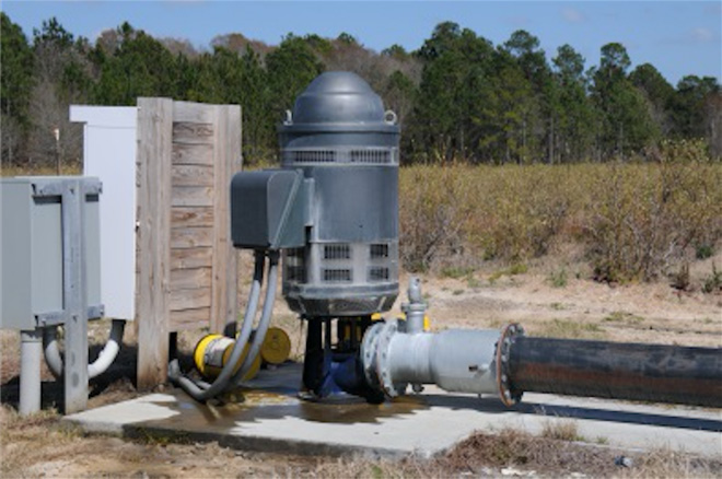
Figure 3. Turbine pump assembly with electrical motor.
Suction (intake) lines (for surface water)
Verify that the intake line and screen are clear, that the intake line is properly supported, and check for and fix any leaks. If possible, pull the pipe out of the water and check on the condition of all suction components. Intakes should not be positioned at the bottom of a pond, as they can pick up debris or plant pathogens that survive in the mud at the bottom of a pond.
Piping and drains
Close all manual pump station drains, verify that control valves are working properly, and inspect aboveground pipes, gaskets, and seals.
Electrical systems
ELECTRICITY KILLS. Use proper safety procedures when checking these systems.
Generally, electrical pumps for irrigation are run with alternating current (AC) at 60 Hz (cycles per second). For greater water demand voltages—as high as 480 V—three-phase electrical power sources are used to run motors.
The ampere (amp) is a measure of energy or electricity moving (current) through the line. It is the ampere that makes muscles contract, causing the hand to grab on to a live electrical line and not let go. At 30 mA being pushed at 60 cycles, sustained contact can cause tissue damage and lead to ventricular fibrillation, heart attack, or death. Good safety practices include using a lock-out/tag-out system, keeping systems properly grounded, and maintaining a properly functioning multimeter.
When first handling electrical fixtures, fill out tags, put locks on the breakers, wear rubber soled shoes, and remember that the first item to enter a fixture, service box, or controller should be the probes of the volt meter to check if any of the lines are hot.
Once this is done, inspect and replace all damaged wires. Then tighten all contacts. Resistance, which is measured in ohms, results in heat. As metal heats and cools, contacts loosen and create greater resistance. This increased resistance can cause fuses to blow and breakers to trip. Look for signs of burns, water leaks, and wear on individual components.
In the field
Inspect the zones, check valves for proper operation, and inspect air valves, which sometimes have critters nesting in them. Identify and replace any damaged components.
If the drip line is sub-surface or under mulch, thoroughly inspect the rows for signs of critter movement. For example, deer may tear the drip line with their hooves, coyotes may chew on the drip line, and mice may nibble plastic parts.
When you’ve identified damage, use flagging to mark the spot, and when charging the system, return to the flagged spot to see if leaks have occurred.
Operational Checklist
Turn on the system.
Pressure
- Verify proper pressure readings at the pump and across the filter (Figures 4 and 5). A pressure drop across the filter indicates that the filter needs to be cleaned.
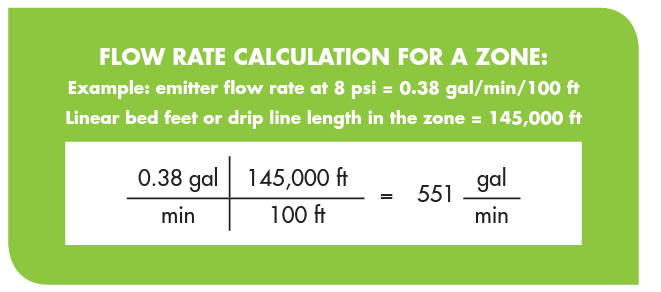
- Check flow meter for proper operation (see flow rate calculation).
- After checking the pressure regulator, check the pressure gauge to ensure that the pressure does not exceed the manufacturer’s recommended specifications for the drip line, usually around 10 psi.
- If the pressure level looks good, run the system with the field drains open and the ends of the drip lines open. After an adequate amount of water has flowed through the system, close the field drains to allow water to move through the drip lines, and check each drip line for outflow. Lines with no flow could be severed, kinked, and/or clogged, and repairs are necessary.
- Close up the system and test each block. Travel the length of each drip line looking for leaks. To reduce unwanted trips, carry a repair kit with drip line couplers, extra tubing, a shovel, tools, and a razor knife. To make straight cuts that enable the couplers to seal, carry a 6- to 12-inch piece of 2x4 and make cuts to the drip line on it. If an extra trip is necessary, place flagging at the spot you left off so it is easier to find when you return.
Note: if using flagging, remove it after you are finished with your task to alleviate confusion. Use a code system with different colors or patterns to separate tasks. For example, use orange flagging on block x for drip line repair on date x, and use blue flagging to mark the row you are presently working on. All related flagging should be removed when the task is complete.
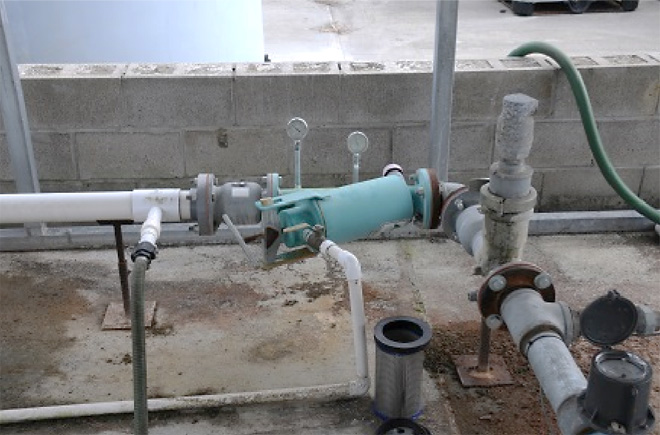
Figure 4. Filter, gauges, and air relief valve. Note flow meter in foreground.
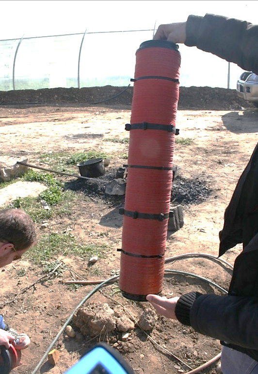
Figure 5. Sand that accumulates in disk filters can negatively impact filtering capacity and performance.
System flow
To ensure that the system has not been clogged with salts during the winter, it is useful to do a quick estimate of the system flow. All drip tape or emitters come with a standard flow rate at a specific pressure. A common drip tape flow rate might be 0.38-gal/min/100 ft at 8 psi. In an irrigation block with approximately 145,000 linear bed feet, your irrigation system should be using roughly 551 gallons per minute.
If your flow rate is significantly lower than the common flow rate, you may have a large number of clogged emitters. Conversely, if your flow rate greatly exceeds your estimate, you might have a large number of leaks. Acids can be used to remove scaling and salt buildup from drip systems.
Chemigation System Start-Up Checklist
Chemical injection systems are available in simple to sophisticated systems that apply exact amounts of product. However, they all need maintenance and a thorough inspection before operation.
If injecting acid, use extreme caution when working with the system, and wear a face shield, acid-resistant rubber gloves, and an acid-resistant apron. In addition, have an eyewash and safety shower immediately accessible.
Even when working on a non-acid injection system, the proper protective gear should be used to prevent exposure to the products being injected. The personal protective equipment (PPE) is listed on the label of the product and is a function of the product’s chemistry.
Always use the highest level of PPE recommended from the label to minimize the risk of exposure. Remember that the injection system has the most concentrated formula passing through it!
Venturi injectors (Figure 6)
Inspect the connections, suction line, valves, venturi injector, and filter at the end of the suction line. Replace as needed. If the system has been left out through the winter, closely inspect it for weathering, cracks, and any other damage.
Before using the injector, test it with water. Place the suction line (with filter attached) in a bucket of water. Run the irrigation system, and note how long a known amount of water is being drawn into the irrigation system at different settings. Noting the line pressure and drawdown time can be used to calibrate the system. While the suction line is in the bucket, shut off the valves to the injector. If the system is still drawing or back flushing water, replace the valves.
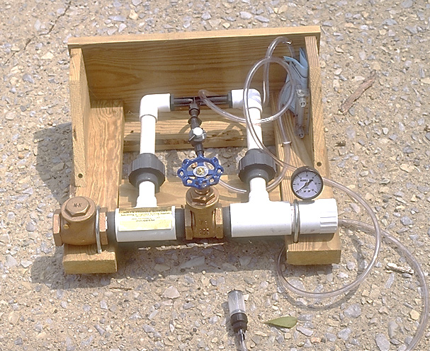
Figure 6. Fittings on the venturi injector, usually made of plastic, should be inspected for weathering.
Mechanical pumps
Use the manufacturer's recommendations for servicing your unit. Inspect and clean around the unit. Look for cracks, weathering, and dirt, and replace and clean where necessary. Inspect the valves and couplers from the feed tanks to the pump.
In Figure 7, a variable in-line flow meter is being used for chemigation. The manufacturer’s website provides technical data sheets with recommended maintenance for each of its models. Like the venturi injectors, use water to test for leaks and operation of the mechanical injectors, and calibrate to ensure that the correct proportions are being delivered to your plants.
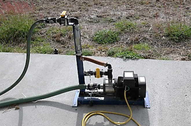
Figure 7. Centrifuge pump with electric motor and a Blue-White® variable in-line flow meter.
Status and Revision History
Published on Aug 04, 2016
