Agricultural sprayers are commonly used for pesticide applications and come in various design types and sizes, including three-point hitch, pull-behind, and self-propelled. During pesticide applications, maintaining a target application rate (in gallons per acre or GPA) across the whole field is important for effective pest management. Fluctuations in ground speed are common when applying pesticides with agricultural sprayers because of variations in field topography or as soil and crop conditions change within a field. These speed changes also require changes in liquid flow rates to maintain the preselected target application rate. On sprayers with traditional flow-based control systems, the liquid flow rate is regulated to account for ground speed variations by adjusting the spray pressure. However, this becomes an issue when spray pressure reaches outside the narrow operating range of the selected nozzle and results in non-uniform spray quality (droplet size) and pattern. Higher spray pressures at faster travel speeds produce finer droplets which are more prone to spray drift; applications at lower pressures, especially below a set minimum point, produce coarser spray droplets and reduce spray fan angle.
Pulse width modulation (PWM) technology for agricultural sprayers was developed to overcome this pressure variation issue—PWM does not rely on spray pressure to regulate system flow rate with changes in ground speed. In PWM systems, the flow rate is varied by changing the intermittent cycling (duty cycle) of the electronically actuated solenoid valves while the system pressure remains constant throughout the boom.
Figure 1 shows an example of operational difference among nozzles in a conventional versus a PWM system. On a traditional sprayer, a nozzle is always in open-state (ON) during field application whereas the nozzle in a PWM system cycles between open- and closed-state (ON/OFF) continuously at a high frequency (10–20 Hz) to deliver the target application rate. With variations in the sprayer ground speed, the amount of time per second the nozzle is in open-state (i.e., spraying) changes to vary the flow rate. Since spray pressure in the boom remains constant in a PWM system, this helps maintain a uniform spray pattern and quality. Thus, PWM spray technology enables more precise and efficient pesticide applications through improved control over both flow rate and pressure.
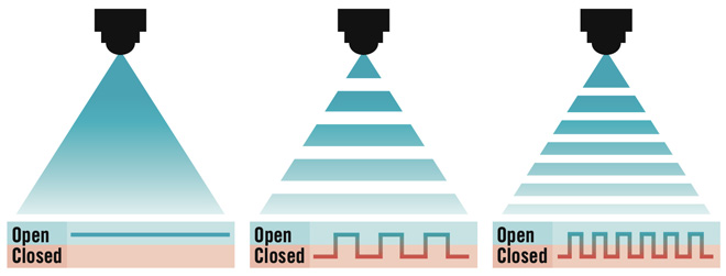
Figure 1. Illustration of the (a) always-open-state (ON) of a nozzle on a conventional spray system versus (b and c) open-state and closed-state (ON/OFF) at two different duty cycles in a PWM system.
Pulse Width Modulation System Components
The main components of a PWM system on an agricultural sprayer are solenoid valves, valve driver/module, electronic control unit, GPS/DGPS, and an in-cab display/computer. Each of these components are explained below.
Solenoid valves are installed on individual nozzle bodies across the whole length of the sprayer boom to regulate nozzle flow based on the selected PWM duty cycle. These valves also provide individual nozzle control (ON/OFF) capabilities.
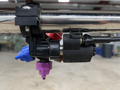
The valve driver/control module is used to provide power and send PWM commands to the individual solenoid valves. Each valve driver can connect to and control six to 10 solenoid valves at a time, so multiple valve drivers/control modules generally are installed along the length of the sprayer boom.

An electronic control unit (ECU) is used to send control and receive feedback signals from different sensors present on the sprayer including solenoid valves, pressure sensor, and flow meter. An ECU acts as the main gateway on the sprayer that connects and receive signals from different PWM system components.

A GPS/DGPS is used to determine the spatial location and speed of the sprayer during field operation. This information is used to regulate the flow rate as needed as well as to turn the solenoid valves ON/OFF to prevent skips and overlap. A GPS/DGPS also is used to determine the speed of individual solenoid valves, especially during turns, to maintain the target application rate across the whole boom.

An in-cab display/computer is used to input application parameters such as target rate (GPA) and pressure, as well as monitor performance of the PWM system during application. It also is used to diagnose and troubleshoot issues with individual solenoid valves and other PWM system components.

System Operation
The operation of a PWM system is based on two main principles to regulate the flow rate: duty cycle and frequency of the solenoid valves.
A duty cycle is the proportion of the time that a solenoid valve is open or ON, meaning the percentage of time a spray nozzle actually is spraying. For most commercial systems, the typical duty cycle ranges between 20% and 100%. For example, a nozzle operating at a 100% duty cycle means it’s fully open and delivering maximum flow, whereas a nozzle operating at a 40% duty cycle will deliver about two fifths of the maximum possible flow. Figure 2 illustrates a PWM system operating at different duty cycles and a constant frequency of 10 Hz. Because duty cycle is directly related to the nozzle flow rate, a decrease in duty cycle lowers the application rate by reducing the amount of time a nozzle is open/ON and vice-versa.
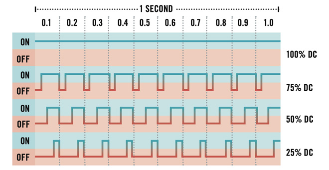
Figure 2. Illustration of a PWM system operation at different duty cycles (labeled as % DC) at 10 Hz frequency.
The frequency of a solenoid valve is the number of ON/OFF cycles completed in 1 s (Hertz), i.e., how fast the valve is cycling every second. For example, a PWM nozzle operating at a frequency of 10 Hz will close and open 10 times in a second, while a nozzle operating at 20 Hz will close and open 20 times in a second. The available frequency range on commercial PWM systems typically is from 10 Hz to 30 Hz, while 10 or 20 Hz is the most commonly used frequency during spray applications.
Figure 3 illustrates the operation of a PWM system at different frequencies with a constant duty cycle of 50%. As frequency changes only the number of ON/OFF cycles every second, an increase or decrease in operating frequency does not affect the nozzle flow rate as long as the duty cycle of the system remains constant. The cycling of the solenoids occurs so fast that it does not adversely affect spray pattern and quality.
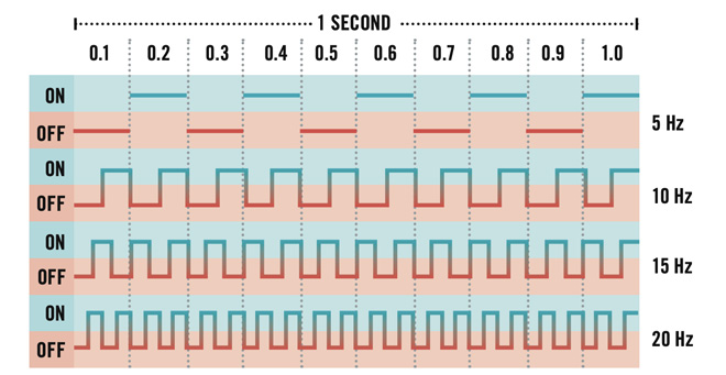
Figure 3. Illustration of PWM system operation at different frequencies at a 50% duty cycle.
Even though the nozzles on the spray boom are turning ON and OFF (based on the duty cycle) at a high frequency (10–30 Hz) during operation of a PWM system, there is potential for skips in the application if all nozzles are coming ON/OFF simultaneously. To avoid that issue, all commercial PWM systems utilize a blended pulse (Figure 4), which means that every other nozzle operates at an alternate frequency across the spray boom (i.e., two adjacent nozzles on the boom are never completely off at the same time during application).
Even though the nozzles on the spray boom are turning ON and OFF (based on the duty cycle) at a high frequency (10–30 Hz) during operation of a PWM system, there is potential for skips in the application if all nozzles are coming ON/OFF simultaneously. To avoid that issue, all commercial PWM systems utilize a blended pulse (Figure 4), which means that every other nozzle operates at an alternate frequency across the spray boom (i.e., two adjacent nozzles on the boom are never completely off at the same time during application).
Since each nozzle in a PWM system is controlled individually by a solenoid valve, this technology provides the capability for individual nozzles to turn on and off to prevent skips and overlap during application. The response time of a PWM system to change the nozzle flow rate and the time for individual nozzles to turn on and off also is significantly faster (Sharda et al., 2016) when compared to the time needed for flow-rate regulation and section control on a conventional spray system.
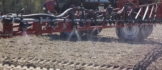
Figure 4. A PWM system using blended pulse on a sprayer boom. Observe that every other nozzle is operating at an alternate frequency.
Benefits of Pulse Width Modulation Technology
The PWM spray technology provides several benefits compared to the traditional flow-based control systems on agricultural sprayers. Some of these benefits are:
- Fast and precise flow rate changes with variations in ground speed.
- Improved control of system flow and pressure.
- Individual nozzle control enabling more precise application.
- Variable-rate application capabilities through varying the duty cycle.
- Consistent nozzle spray pattern and droplet size.
- Ability to monitor droplet size during application.
- Turn compensation by varying the duty cycle of inside and outside nozzles.
Best Management Practices for Pulse Width Modulation Sprayers
Since the mode of operation of PWM technology is different from traditional flow-based control systems, it requires careful selection of several application parameters (Butts & Gruger, 2018). The following best management practices should be considered to effectively utilize PWM technology on agricultural sprayers:
Nozzle selection: Follow nozzle manufacturers’ guidelines to select proper nozzles for PWM systems. Additionally, use only nozzles recommended by the sprayer and/or nozzle manufacturer with PWM systems. Some air-induction (AI) nozzles can exhibit fluctuations in spray pressure and poor spray quality because of their Venturi effect. Therefore, only manufacturer-approved AI nozzles should be used with PWM systems.
Operation at lower duty cycles: The typical duty cycle range for most PWM systems is between 20% and 100%. While lower duty cycles (< 20%) are possible during application, they are not recommended because of inconsistent spray pattern and quality. Duty cycles above 50% are considered ideal for PWM systems to work efficiently and should be considered during nozzle selection along with the nominal ground speed of the sprayer during application.
Operating pressure: While lower pressures (20–30 psi) generally are used for producing coarser droplets in traditional spray systems, a PWM system operating at a lower pressure can result in poor application performance; pressure loss across a solenoid valve considerably increases with an increase in nozzle orifice size. A large pressure loss can result in actual boom pressure being below the manufacturer’s recommended operating pressure and can affect both application rate and spray quality. PWM systems should be operated between 40–50 psi for best system performance.
Commercially Available Pulse Width Modulation Systems
Currently, several equipment manufacturers and technology companies offer PWM technology as factory equipped or retrofit options for a wide range of agricultural sprayers. Here is a list of commercially available PWM systems:
Teejet Technologies: DynaJet Flex 7140
Raven Industries: Hawkeye Nozzle Control
Capstan Ag: PinPoint II
John Deere: ExactApply
Ag Leader: RightSpot
Case IH: AIM Command FLEX
Summary
Pulse width modulation technology on agricultural sprayers helps achieve better application accuracy and efficiency through improved control over both flow rate and spray pressure during field operation. The benefits of PWM technology are maximized in uneven and irregular fields where travel speed fluctuations and turns are more frequent. For optimal utilization of PWM technology on agricultural sprayers, it is important for users to carefully follow manufacturer recommendations on proper selection of application parameters such as nozzle size, spray pressure, and range of duty cycles.
Status and Revision History
Published on Dec 20, 2022
