John Worley, Professor
Department of Poultry Science
Greenhouses should provide a controlled environment for plant production with sufficient sunlight, temperature and humidity. Greenhouses need exposure to maximum light, particularly in the morning hours. Consider the location of existing trees and buildings when choosing your greenhouse site. Water, fuel and electricity make environmental controls possible that are essential for favorable results. For this reason, use reliable heating, cooling and ventilation. Warning devices might be desirable for use in case of power failure or in case of extreme temperatures.
The house temperature requirements depend upon which plants are to be grown. Most plants require day temperatures of 70 to 80 degrees F, with night temperatures somewhat lower. Relative humidity may also require some control, depending on the plants cultured.
Some plants grow best in cool greenhouses with night temperatures of 50 degrees F after they are transplanted from the seeding tray. These plants include azalea, daisy, carnation, aster, beet, calendula, camellia, carrot, cineraria, cyclamen, cymbidium orchid, lettuce, pansy, parsley, primrose, radish, snapdragon, sweet pea and many bedding plants.
Some plants grow best in warm greenhouses with night temperatures of 65 degrees F. These plants include rose, tomato, poinsettia, lily, hyacinth, cattleya orchid, gloxinia, geranium, gardenia, daffodil, chrysanthemum, coleus, Christmas cactus, calla, caladium, begonia, African violet, amaryllis and tulip.
Tropical plants usually grow best in high humidity with night temperatures of 70 degrees F.
Heating
Georgia greenhouses must be heated for year-round crop production. A good heating system is one of the most important steps to successful plant production. Any heating system that provides uniform temperature control without releasing material harmful to the plants is acceptable. Suitable energy sources include natural gas, LP gas, fuel oil, wood and electricity. The cost and availability of these sources will vary somewhat from one area to another. Convenience, investment and operating costs are all further considerations. Savings in labor could justify a more expensive heating system with automatic controls.
Greenhouse heater requirements depend upon the amount of heat loss from the structure. Heat loss from a greenhouse usually occurs by all three modes of heat transfer: conduction, convection and radiation. Usually many types of heat exchange occur simultaneously. The heat demand for a greenhouse is normally calculated by combining all three losses as a coefficient in a heat loss equation.
Conduction
Heat is conducted either through a substance or between objects by direct physical contact. The rate of conduction between two objects depends on the area, path length, temperature difference and physical properties of the substance(s) (such as density). Heat transfer by conduction is most easily reduced by replacing a material that conducts heat rapidly with a poor thermal conductor (insulator) or by placing an insulator in the heat flow path. An example of this would be replacing the metal handle of a kitchen pan with a wooden handle or insulating the metal handle by covering it with wood. Air is a very poor heat conductor and therefore a good heat insulator.
Convection
Convection heat transfer is the physical movement of a warm gas or liquid to a colder location. Heat losses by convection inside the greenhouse occur through ventilation and infiltration (fans and air leaks).
Heat transfer by convection includes not only the movement of air but also the movement of water vapor. When water in the greenhouse evaporates, it absorbs energy. When water vapor condenses back to a liquid, it releases energy. So when water vapor condenses on the surface of an object, it releases energy to the outside environment.
Radiation
Radiation heat transfer occurs between two bodies without direct contact or the need for a medium such as air. Like light, heat radiation follows a straight line and is either reflected, transmitted or absorbed upon striking an object. Radiant energy must be absorbed to be converted to heat.
All objects release heat in all directions in the form of radiant energy. The rate of radiation heat transfer varies with the area of an object, and temperature and surface characteristics of the two bodies involved.
Radiant heat losses from an object can be reduced by surrounding the object with a highly reflective, opaque barrier. Such a barrier (1) reflects the radiant energy back to its source, (2) absorbs very little radiation so it does not heat up and re-radiate energy to outside objects, and (3) prevents objects from “seeing” each other, a necessary element for radiant energy exchange to occur.
Factors Affecting Heat Loss
Heat loss by air infiltration depends on the age, condition and type of greenhouse. Older greenhouses or those in poor condition generally have cracks around doors or holes in covering material through which large amounts of cold air may enter. Greenhouses covered with large sheets of glazing materials, large sheets of fiberglass, or a single or double layer of rigid or flexible plastic have less infiltration (Figure 1).
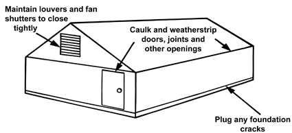 Figure 1.
 Energy loss due to infiltration.
The greenhouse ventilation system also has a large effect on infiltration. Inlet and outlet fan shutters often allow a large air exchange if they do not close tightly due to poor design, dirt, damage or lack of lubrication. Window vents seal better than inlet shutters, but even they require maintenance to ensure a tight seal when closed.
Solar radiation enters a greenhouse and is absorbed by plants, soil and greenhouse fixtures. The warm objects then re-radiate this energy outward. The amount of radiant heat loss depends on the type of glazing, ambient temperature and amount of cloud cover. Rigid plastic and glass materials exhibit the “greenhouse effect” because they allow less than 4 percent of the thermal radiation to pass back through to the outside.
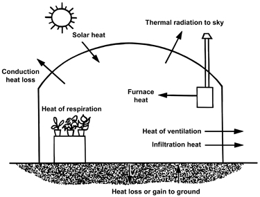 Figure 2.
 Energy losses and gains in a greenhouse.
Heat Loss Calculations
Heat loss by conduction may be estimated with the following equation:
Q = A (Ti - To)/R
Where:
Q = Heat loss, BTU/hr
A = Area of greenhouse surface, sq ft
R = Resistance to heat flow (a characteristic of the material)
(Ti-To) = Air temperature differences between inside and outside
Table 1 lists different materials commonly used in greenhouse construction and their associated R values. Table 1 also lists overall R values for various construction assemblies. Note that high R values indicate less heat flow. Building materials that absorb moisture will conduct heat once they are wet. Use vapor barriers to protect materials that are permeable to water vapor. Heat is also lost to the ground underneath and beside a greenhouse. The perimeter heat loss may be added to other losses using Table 1 and the equation:
Q = PL (Ti - To)
P = Perimeter heat loss coefficient, BTU/ft ºF hr
L = Distance around perimeter
| Table 1. Heat Flow Through Various Construction Materials and Assemblies. |
| Materials |
R-Value |
| Glass fiber board, 1" |
4.0 |
| Expanded polystyrene, 1", cut surfaces |
4.0 |
| Expanded polystyrene, 1", smooth skin surface |
5.0 |
| Expanded polystyrene, molded beads, 1" |
3.6 |
| Expanded polyurethane, 1" |
6.2 |
| Vermiculite, 1" |
2.2 |
| Glass fiber blanket, 3-3.5" |
11.0 |
| Glass fiber blanket, 5.0-6.5" |
19.0 |
| Wall Materials |
| Concrete block, 8" |
2.00* |
| Plywood, ½” |
1.43* |
| Concrete, poured, 6" |
1.25* |
| Concrete block or plywood, plus 1" foamed urethane |
7.69* |
| or plus 1" polystyrene |
5.0* |
| Greenhouse with thin thermal curtains |
1.42-3.33* |
| Construction Assemblies |
| Material |
Overall R-Value |
| Roof and Wall Coverings |
| Glass, single layer |
0.91* |
| Glass, double layer, ¼” space |
2.00* |
| Polyethylene or other film, single layer |
0.83* |
| Polyethylene or other film, double layer separated |
1.43* |
| Polyethylene film, double layer, separated, over glass |
2.00* |
| Fiberglass reinforced pane |
0.83* |
| Double acrylic or polycarbonate |
2.00* |
| Perimeter |
Btu/linear ft ºF hr |
| Uninsulated |
0.8 |
| Insulated |
0.4 |
| *Includes effects of surface coefficients. |
Add infiltration heat losses to the conduction heat losses. The equation for infiltration heat transfer follows:
Q = 0.02 V C (Ti - To)
V= Greenhouse volume, cu ft
C = Number of air exchanges per hour
Table 2 lists estimates of air exchanges through types of greenhouses. The number of air exchanges per hour will vary depending on the type and condition of the greenhouse and the amount of wind.
| Table 2. Natural Air Exchanges for Greenhouses |
| Construction System |
Air Exchanges per Hour1 |
| New Construction, glass or fiberglass |
0.75 to 1 |
| New Construction, double layer plastic film |
0.5 to 1.0 |
| Old Construction glass, good maintenance |
1 to 2 |
| Old Construction glass, poor condition |
2 to 4 |
| 1Low wind or protection from wind reduces the air exchange rate. |
Minimum Design Temperatures
A good outside temperature to use in heater design calculations (to select heater size) can be found by subtracting 15 degrees F from the average daily minimum January temperature (see Table 3). Another requirement the heater must meet is to provide enough heat to prevent plants from freezing during periods of extremely low temperatures. The minimum temperatures for various locations within Georgia are also shown in Table 3.
| Table 3. Climatic Conditions in Georgia (1948-2004) |
| Location |
Minimum Temperature ºF and (Year Occurring) |
Average Daily Minimum January Temperatures (ºF) |
| Atlanta |
-8 (1985) |
33.6 |
| Athens |
-4 (1985) |
33.2 |
| Augusta |
-1 (1985) |
33.6 |
| Columbus |
-2 (1985) |
36.4 |
| Macon |
-6 (1985) |
35.8 |
| Rome |
-9 (1985) |
30.5 |
| Savannah |
3 (1985) |
39.0 |
| Tifton |
0 (1985) |
38.0 |
| Valdosta |
9 (1981) |
38.6 |
Example:
Maintain a temperature of 65 degrees F inside a double layer plastic greenhouse with dimensions as shown in Figure 3 with no foundation insulation. Assume an Augusta location.
| Surface Area: |
| Walls |
7 x 100 x 2 |
= |
1400.0 ft² |
| Roof |
16.86* x 100 x 2 |
= |
3372.0 ft² |
| Ends |
(32 x 7 + 5.33 x 16)2 |
= |
618.6 ft² |
| |
|
|
5390.6 ft² |
| * This dimension can be determined by drawing the greenhouse cross-section to scale and measuring this length along the rafters. |
At an Augusta location and an average daily minimum January temperature of 33.6 degrees F, the design temperature would be about 18.6 degrees F, so use 20 degrees F. This requires a 45-degree F rise above design temperature; and, with double layer plastic, the R-value will be 1.43.
| Conduction Heat Loss, QC: |
= Area x ΔT/R
= 5391.0 x 45/1.43
= 169,647 BTU/hr
|
| Volume: |
= (7 x 32 x 100) + (16 x 5.33 x 100)
= 22,400 + 8,528
= 30,928 ft³
|
| Air Infiltration Losses, QA: |
= 0.02 x Volume x C x ΔT
= 0.02 x 30,928 x 1.0 x 45
= 27,835 BTU/hr
|
| Perimeter Heat Loss, QP: |
= P x L x (ΔT)
= 0.8 x 264 x 45
= 9,504 BTU/hr
|
| Total Heat Loss, QT: |
= QC + QA + QP
= 169,647 + 27,835 + 9,504
|
| Heat Required = 206,986 BTU/hr |
The coldest temperature recorded in Augusta is -1 degree F and, with a 45-degree F temperature rise, the plants should not be in jeopardy from freezing. An increase in heat requirement of approximately 20 percent would be necessary if the house were located on a windy hill.
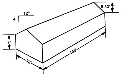 Figure 3.
 Gable double layer polyethylene greenhouse.
Other Heating System Design Considerations
Plastic greenhouses often have a humidity buildup within the enclosure since almost no cracks or openings exist as in a glass house. High humidity can lead to increased occurrence of leaf and flower diseases. A forced air heating system helps mix the air within the house and helps prevent temperature variation within the house. In fact, it is desirable to have fans along the walls to circulate and mix the warm air with the cooler air near the surface. They can be operated continuously during cold periods even if the heater is not on.
Duct systems to evenly distribute the heated air from the forced warm air furnace are desirable. Two or more small heating units are preferable to one larger unit, since two units offer more protection if one unit malfunctions.
A warning device is good insurance should the heating system malfunction or if a power failure occurs. Some greenhouse operators prefer to have a battery powered alarm system to warn them if the temperature gets out of the acceptable range.
Ventilation
Ventilation reduces inside temperature during sunny days and supplies carbon dioxide, which is vital to the plants’ photosynthesis. Another advantage of ventilation is to remove warm, moist air and replace it with drier air. High humidity is objectionable since it causes moisture condensation on cool surfaces and tends to increase the occurrence of diseases.
Some glass houses are ventilated by manually operated ventilators in the roof. This method is usually not satisfactory for ventilating plastic covered houses due to the rapid temperature fluctuations possible. Ventilating fans are highly recommended in Georgia.
Winter ventilation should be designed to prevent cold drafts on plants. This has been a problem with some systems using shutters at one end of a house and an exhaust fan at the other. The problem can be minimized by placing the intake high in the gable and using baffles to deflect the incoming air.
Draft-free winter ventilation can be provided by using the convection tube system, consisting of exhaust fans and fresh air inlets located in the gable and end wall. This is connected to a thin plastic tube extending the length of the greenhouse. The tube is suspended on a wire near the ridge and has holes along its entire length. The fans can be thermostatically controlled. Fan operation produces a slight air pressure drop inside the greenhouse, causing fresh air to flow into the inlet and inflate the tube, which discharges air into the house through the holes in the tube. The holes emit “jets” of air that should project horizontally to provide proper distribution and mixing with warm air before reaching the plants.
The thermostat stops the fans when the desired temperature is reached; the tube collapses and ventilation stops. In a tightly constructed greenhouse, it makes little difference where fans are located in convection tube ventilation since the air distribution is determined by the tubes. Less fan capacity is usually required for the convection tube system than for any other winter ventilation system. Additional air is necessary as the outdoor temperature rises to the point where full capacity of the tube is reached. The outside air is usually warm enough by this time to be admitted through doors or other openings at plant level.
Fans may be added or possibly combined with a cooling pad for use in evaporative cooling. In fact, air may be pulled through the pad with or without water in the pad. In warm periods, enough air needs to be pulled from the house to provide a complete air exchange every 60 seconds. Control fans by a thermostat or humidistat to provide proper temperature and humidity.
Greenhouses equipped with an evaporative cooling pad system having three fans or fewer should have one fan with a two-speed motor to prevent excessive temperature fluctuations and fan cycling. Select all fans to operate against a slight pressure (? inch static water pressure). Fans not rated against slight pressure usually move only 60 to 70 percent of the rated air flow when installed in greenhouses. It is recommended that only fans that have been tested and their performance verified by an independent testing lab, such as AMCA, be used, since that is the only assurance that the design ventilation rate is being achieved.
Exhaust Fans in End Wall
Fans in the end wall (Figure 4) are the most common method of forced ventilation. The air enters through the motorized shutter (winter) and is pulled through the greenhouse by the exhaust fans.
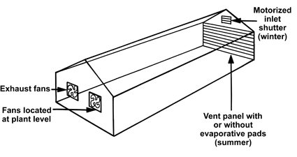 Figure 4.
 Fans in end wall.
The exhaust fans should be able to move small air volumes without drafts (winter) and yet provide enough fan capacity for an air exchange within the house each minute during summer. One air exchange per minute (without evaporative cooling) should keep the temperature about 8 degrees F higher than outside temperatures. One-half of this air volume will produce about a 15-degree F temperature rise, while two air exchanges per minute will cause a temperature rise of about 5 degrees F. Ideally, the length of the house should not exceed 125 feet using this method. Houses up to 250 feet long, however, have been satisfactorily ventilated using this method. Temperature variations are greater in longer houses, so higher ventilation rates are desirable. No air must be allowed to enter the house at the sides or at the fan end.
Glazing in glass houses must be well set and the houses in good repair to prevent significant quantities of air leaking into the house. If cooling pads are used during summer, disconnect the motorized shutter and close it to prevent hot air from entering through the shutter and bypassing the cooling pads. You can connect a perforated plastic tube to the same inlet shutter to provide good air distribution for cold weather ventilation.
The same principle applies for multiple ridge houses, provided each end wall is so equipped. One two-speed fan is usually used in small hobby houses.
The total inlet opening in the end wall for summer ventilation (shutter and evaporative pad vent) should provide about 1.5 square feet per 1,000 cubic feet per minute of air moving through the operating fans. The motorized shutter and one or two fans might be connected on one thermostat while the remaining fans are connected to a different thermostat, with air being supplied to these fans through the vent panel containing the evaporative pad.
Pressure Fans in End Walls
Ventilation for greenhouses that are 100 feet or shorter can be accomplished by mounting pressure fans, which blow air into the house, high in the end walls. See Figure 5.
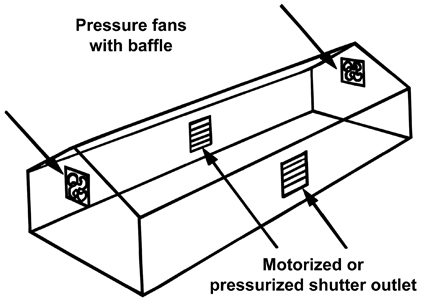 Figure 5.
 Pressure fans mounted high in the end walls.
The fans in the end wall are usually two-speed and controlled by separate thermostats. To avoid high velocity air striking plants, a baffle is placed in front of the fans to direct the air in the direction desired. The fans should have a protective hood to prevent rain from being blown into the house.
One pressurized system where evaporative cooling is possible is shown in Figure 6. This system places the pressure fans in the side wall. The pressurized system with fans in the side wall does not work well when the foliage is dense and lots of tall, growing plants are present. Notice the air outlet and inlet are on the same side of the house in this case, with a box enclosure around the fan where cooling pads are installed.
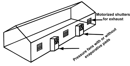 Figure 6.
 Pressure fans mounted in the sidewalls.
Evaporative Cooling
The heat absorbed on a dark surface perpendicular to the sun’s rays can be as high as 300 BTU/HR per square foot of surface. So it would be possible, theoretically, for a greenhouse to absorb 300 BTUs per hour for each square foot of floor area. This excessive energy leads to heat buildup and, on warm days, can cause plants to wilt.
Excessive heat buildup can often be prevented with shading materials such as roll-up screens of wood, aluminum or vinyl plastic as well as paint-on materials (shading compounds). Roll-up screens, which work well in hobby houses, are available with pulleys and rot-resistant nylon ropes. These screen can be adjusted from outside as temperature varies. Radiation can be reduced by 50 percent with this method, which should reduce temperature rise proportionally if ventilation rate remains constant. Shading also reduces light striking the plants, which may limit their growth rate since light is essential to photosynthesis. This is a trade-off that is sometimes necessary to reduce temperatures.
If summer temperatures exceed those considered acceptable and cannot be corrected with reasonable ventilation rates and shading, the only alternative is evaporative cooling. A fan and pad system using evaporative cooling eliminates excess heat and adds humidity. This reduces plant moisture losses and, therefore, reduces plant wilting. Temperature is lowered, humidity is increased and watering needs are reduced.
An evaporative cooling system moves air through a screen or spray of water in such a manner that evaporation of water occurs. About 1,000 BTUs of heat are required to change 1 pound of water from liquid to vapor. If the heat for evaporation comes from the air, the air is cooled. Evaporation is greater when the air entering the system is dry; that is, when the relative humidity is low, allowing the air to evaporate a lot of water. The water holding ability of air is expressed in terms of relative humidity. A relative humidity of 50 percent, for example, means the air is holding one-half of the maximum water that the air could hold if saturated at a given temperature.
Theoretically air can be cooled evaporatively until it reaches 100 percent relative humidity. Practically, a good evaporative cooler can reach about 85 percent of this temperature drop. The cooling effect for 85 percent efficient evaporative coolers is shown in Table 4.
Evaporative coolers are more effective when the humidity is low (Table 4). Fortunately, relative humidities are usually low during the warmest periods of the day. Solar heat entering the house offsets some of the cooling effect. A well-designed ventilation system pro-viding one air volume change per minute is essential for a good evaporative cooling system. A solar heat gain of 8-10 degrees F can be expected using one air change per minute. If the outside air were 90 degrees F and relative humidity were 70 percent, the resulting temperature within the house would be about 93 degrees F (83 degrees F from Table 4 plus 10 degrees F).
| Table 4. Cooling Capacity of 85 Percent Efficient Evaporative Coolers |
| Outside Air |
Relative Humidity |
| at 30% |
at 50% |
at 70% |
at 90% |
| Outside Air Temperature ºF |
Cooled Air Temperature ºF |
| 100 |
79 |
86 |
91 |
96 |
| 90 |
70 |
77 |
83 |
87 |
| 80 |
63 |
69 |
74 |
77 |
| 70 |
54 |
60 |
64 |
68 |
If a cooling efficiency of 85 percent is to be realized, at least 1 square foot of pad area (aspen fiber) mounted vertically should be provided for each 150 CFM of air circulated by the fans. Many pad materials have been used successfully, provided a complete water film does not form and block air movement through the wet pad. Table 5 gives recommended air flow through various pad type materials.
| Table 5. Recommended Airflow Rate through Various Pad Materials. |
| Pad Type |
Airflow Rate
through Pad (CFM/ft2) |
| Aspen fiber mounted vertically (2-4 in. thick) |
150 |
| Aspen fiber mounted horizontally (2-4 in. thick) |
200 |
| Corrugated cellulose (4 in. thick) |
250 |
| Corrugated cellulose (6 in. thick) |
350 |
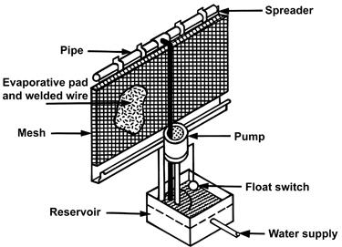 Figure 7.
 Typical evaporative cooling system.
Aspen pads are usually confined in a welded wire mesh. A pipe with closely spaced holes allows water to run down a sheet metal spreader onto the pads (Figure 7). The flow rate of the water supplying header pipe is listed in Table 6. Water than does not evaporate in the air stream is caught in the gutter and returned to a reservoir for recycling. The reservoir should have the capacity to hold the water returning from the pad when the system is turned off. Table 6 shows recommended reservoir capacity for different type pads.
| Table 6. Recommended Water Flow Rate and Reservoir Capacity for Vertically Mounted Cooling Pad Materials. |
| Pad Type |
Min. Flowrate per
Length of Pad (gpm/ft) |
Min. Reservoir Capacity per
Unit Pad Area (Gal/ft2) |
| Aspen fiber (2-4 inches) |
0.3 |
0.5 |
| Corrugated cellulose (4 inches) |
0.5 |
0.8 |
| Corrugated cellulose (6 inches) |
0.8 |
1.0 |
A cover of some sort is needed to prevent air flow through the pads during cold weather. These can be manually operated or automated. Float control easily controls water supply. It is desirable to use an algaecide in the circulating water to prevent algae growth on the pads. You must, therefore, prevent rain water from entering the evaporative cooling water, causing dilution of the chemical mixture.
Evaporative pads in an endome on the suction side of fans that discharge air into houses (pressure fans) have not worked well, primarily due to the distribution of the cooled air. The same is true of package unit evaporative coolers where poor air distribution is concerned. These units can handle air volumes of 2,000 to 20,000 CFM. The problem with them is the difficulty providing uniform cooled air distribution. The closer the units are spaced along the walls, the better the air distribution will be. Package coolers have been used in small houses, and in houses with good air distribution, with considerable success. The pressurized system forces air, which must displace air within the house, into the greenhouse. Vents must be provided for air circulation.
Mist Cooling
Evaporative cooling by spraying tiny water droplets into the greenhouse has met with limited success. The droplets must be tiny, and this requires tiny, closely spaced nozzles operated at relatively high pressures — an expensive design. Water must be well filtered to prevent nozzles from clogging. Uniform distribution of the water droplets throughout the house is difficult to accomplish.
If the mist system carries any minerals in the water, deposits will be left on plant foliage. This accumulation can reduce photosynthesis substantially and can lead to salt toxicity. The mist system can also cause wet foliage, leading to disease problems, particularly when the droplet size is too large.
Mist cooling does not cool as effectively as a conventional evaporative cooling pad system but it is less expensive. The system requires no collection pan or sump. It can cause runoff or puddling beneath the pads if all the water sprayed on the pads is not vaporized.
A system that is actually a combination of a cooling pad and misting (or fogging) system is shown in Figure 8. This is sometimes called a “fogging pad” system. Some growers have used it with success.
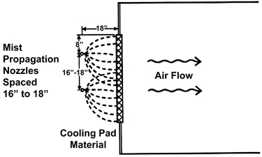 Figure 8.
 Mist nozzle used as evaporative cooling.
The system should provide approximately 20 gallons of water per minute to be sprayed on the pad (typically 20, 1-gpm spray nozzles) for each 48-inch fan in the ventilation system. This amount of water, however, will not always be needed.
Warmer air will evaporate water faster than cooler air. The amount of water added to the pads can be adjusted using a combination of valves, time clocks and thermostats. As the temperature in the greenhouse increases, so does the frequency of mist nozzle operation.
Natural Ventilation
Some greenhouses can be ventilated using side and ridge vents, which run the full length of the house and can be opened as needed to provide the desired temperature. This method uses thermal gradients, creating circulation due to warm air rising.
Houses with only side vents depend upon wind pressure for ventilation and are usually not satisfactory. The warm air must be allowed to rise through the ridge vent while cooler air enters along the sides. The vent size is important. Ridge vents should be about one-fourth the floor area and the side vents about the same size. The roof vents should open above the horizontal position to provide about a 60-degree angle to the roof. Most of these vents are manually operated.
References
AMCA. Air Movement and Control Association International, Inc. 30 West University Dr., Arlington Heights, IL 60004-1893.
ASABE. Engineering Practice. 1993. Heating, Ventilating and Cooling Greenhouses. ASAE EP 406. American Society of Agricultural Engineers. St. Joseph, MI 49085.
Hellickson, M.A., and J. Walker. 1983. Ventilation of Agricultural Structures. American Society of Agricultural Engineers: St. Joseph, MI 49085.
Status and Revision History
Published on Feb 23, 2009
Published on May 14, 2009
Published with Minor Revisions on Nov 23, 2011
Published with Full Review on Dec 03, 2014